Ultrasonics
Our long standing and varied work in Aerospace Composite Inspection has placed us so that we can provide a highly quality service to the yachting industry matching the requirements for the valid inspection of high modulus Carbon components. In the marine field these are typically hulls, decks and components with monolithic structures or spars.
The need for carbon masts to be of light weight but very strong has narrowed the gap between aerospace and marine carbon composites especially where sandwich and high strength monolithic composites are used as the primary structure.
Monolithic Carbon Masts
Large masts require 100% inspection of both the mast half shells and the joints. The optimum method for monolithic carbon is ultrasonics, using as high a frequency as possible to obtain the sensitivity to detect small defects. There is a trade off in penetration into attenuative materials, thicker sections may require the frequency to be lower to effect penetration into the material.
Covering large areas requires extreme concentration when using conventional ultrasonic examination and is prone to error, ineffective coverage and operator fatigue.
Composite Inspection use Ultrasonic Phased Array equipment to reinforce the highly sensitive digital ultrasonic equipment. The Phasor Array enables large coverage and high sensitivity with the ability to detect voids, impact damage and inclusions where backing film has been inadvertently included in the carbon plies.
Mast Inspections
The phased array inspections enable a broad brush inspection using a 64 element at 5MHz frequency that is able to detect very small defects and determine if they are voids, inclusions or resin rich areas of the mast.

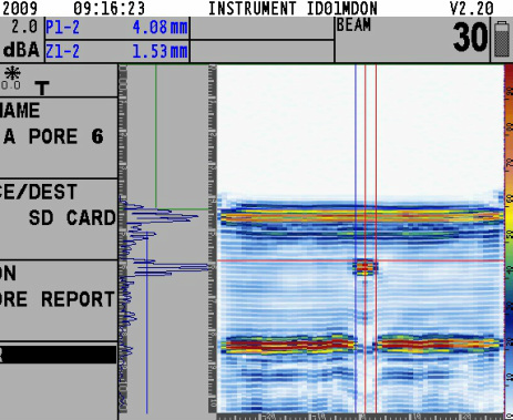
The screen representation below is of a cross section of mast and from which detailed measurements can be taken.
Detailed measurements of defect (1.53mm from inspection surface) and overall width of defect (4.08mm).
Top surface
Defect - Void
Loss of back wall echo indicating the defect is a void
Inner surface of mast
Detailed measurements of defect (1.53mm from inspection surface) and overall width of defect (4.08mm).
Top surface
Defect - Void
Loss of back wall echo indicating the defect is a void
Inner surface of mast

This photograph depicts an inspection by Phased Array with overlapping scans from the sail track to and including the forward joint.
The MCA have recognised the need to regularly inspect carbon masts and have issued a guidance note which can be viewed at - www.dft.gov.uk/mca/417.pdf
Within any carbon fibre structure, such as the mast the pulse of sound energy should be transmitted by the material until it reaches the ‘backwall’ of the structure and be reflected back to the transducer (a backwall echo (BWE)). The time taken for the pulse to reach the backwall is governed by the speed of sound in that material. In a homogeneous material, although some attenuation occurs the passage of sound should be effectively uninterrupted and therefore the trace on the display between the start signal at the surface and the backwall echo would be ‘clean’. In composite materials a number of factors can affect the passage of sound. The indications for ultrasonic instruments can be classified as:-
Disbond / Void – Where the ultrasonic pulse is fully returned by a material-to-air interface at a defect.
Resin Rich Areas – Where the ultrasonic pulse is partially reflected back to the probe as well as being transmitted through the resin to the backwall echo.
Ply Wrinkling – The out of plane deformation of the plies that reflect on the compressive strength and will show ‘wavy’ on a B-Scan image and likely to reduce the backwall signal due to the ply orientation.
Attenuation – Where the material absorbs a proportion of the sound pulse or deflects the pulse away from the transducer due to the internal build of the plies.
Bonded Inclusions – Where foreign extraneous material is included and bonded into the laminate. ie plastic sheet or peel ply. A portion of the sound pulse is likely to be transmitted through this bonded anomaly.
Backwall Echo – Where the signal reaches the far side of the material and is reflected back by the material-to-air interface.
Porosity – Being effectively ‘air’ the porosity will be a large reflector of the ultrasound and is generally seen on a B-Scan as small round indications or on an A-Scan as large signals.

